Hello everyone,
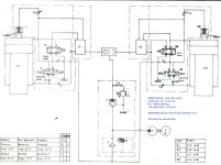
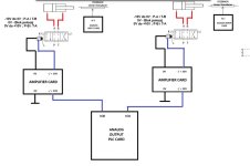
I'm reaching out for assistance regarding a project I'm currently working on. Specifically, it involves a hydraulic system with two cylinders, two servo valves, and two linear transducers for reading the position of the cylinders. I control the servo valves using an Analog Output Card with the PLC.
I have created two operating modes, manual and automatic. Essentially, the machine is functional, but I have one problem. The issue is that I cannot achieve equal movement of the two cylinders (there is always a slight deviation where one lags behind the other). By combining valve activation and setting a specific voltage in the range of -10V to +10V, I achieved fast movement of the press, slow movement - bending, and fast return of the press to its original position.
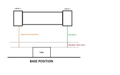
The machine is supposed to have three phases of movement. The first phase involves fast movement to the bending point. The second phase is the bending process itself. The third phase is the return of the press to its initial position. I determine the transitions between these phases based on mathematical calculations in the program, according to readings from the linear transducers of both cylinders (which is working well).
Can anyone help me solve the problem of uneven movement of hydraulic cylinders?
Note: I attempted to implement PI control where I obtained the error signal as the difference between readings from the left and right transducers. Based on the formula for PI control, I obtained the "error" which I added to one cylinder and subtracted from the other, but it did not solve the problem.
Attached you will find an image of the hydraulic schematic along with a brief description, the hardware configuration for controlling the servo valves, and an image illustrating the basic operation of the machine. I am also attaching the datasheet for the servo valves (I have amplifier cards made for controlling the servo valves).
Thank you in advance for your assistance.
I'm reaching out for assistance regarding a project I'm currently working on. Specifically, it involves a hydraulic system with two cylinders, two servo valves, and two linear transducers for reading the position of the cylinders. I control the servo valves using an Analog Output Card with the PLC.
I have created two operating modes, manual and automatic. Essentially, the machine is functional, but I have one problem. The issue is that I cannot achieve equal movement of the two cylinders (there is always a slight deviation where one lags behind the other). By combining valve activation and setting a specific voltage in the range of -10V to +10V, I achieved fast movement of the press, slow movement - bending, and fast return of the press to its original position.
The machine is supposed to have three phases of movement. The first phase involves fast movement to the bending point. The second phase is the bending process itself. The third phase is the return of the press to its initial position. I determine the transitions between these phases based on mathematical calculations in the program, according to readings from the linear transducers of both cylinders (which is working well).
Can anyone help me solve the problem of uneven movement of hydraulic cylinders?
Note: I attempted to implement PI control where I obtained the error signal as the difference between readings from the left and right transducers. Based on the formula for PI control, I obtained the "error" which I added to one cylinder and subtracted from the other, but it did not solve the problem.
Attached you will find an image of the hydraulic schematic along with a brief description, the hardware configuration for controlling the servo valves, and an image illustrating the basic operation of the machine. I am also attaching the datasheet for the servo valves (I have amplifier cards made for controlling the servo valves).
Thank you in advance for your assistance.