Final bit of help on getting DP/DP Coupler Running

EHIRL

Member
Join Date
Mar 2013
Location
Ireland
Posts
13
Right so I have an 315-2DP connected to a DP/DP Coupler on port 2 (158-0AD01-0XA0) just sending 8 Bytes out (only works with consistancy over 'total length'). No errors or error LED's appear and everything seems happy only for the Actual Value in the Datablock not being the same as the initial value despite no changes being implemented?

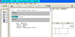
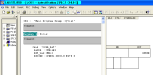
On the other port (1)of the DP is a DeltaV DCS, this is set to pick up the 8 Bytes, when this profibus is cable is connected into the DP Coupler it goes crazy, SF1, SF2, & BF2 Flash and BF1 is always solid regardless. Wiring isn't an issues here though as both sides can see eachother in diagnostics. I then get the error code 32928 on the S7 side saying an error occured accessing data.

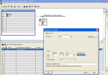
S7 images attached

I'm not too sure where my mistake is here? Any suggestions? Thanks!

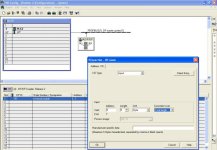
DB1.PNG HW.jpg OB1.PNG
 
http://cache.automation.siemens.com/dnl/DU/DUzNzE1MQAA_1179382_HB/dpdpk_e.pdf

Couple observations -

1. Why are you using the DP Read instruction? The DP/DP I/O will update cyclically already...You would use this instruction to work outside of OB1 in a faster OB to update your process image table.

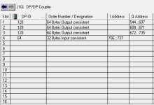
2. Why are you configuring as a Universal Module? I would make it I/O specific, see my screenshot of how I set them up. Not saying it won't work the way it is, it's just I've never set one up like that.

3. You said you felt confident about the cabling. Are you sure you have the termination resistors set to ON for your single cable profibus connections? Rule of thumb I use is if there is a single cable in the connector, enable the resistor. If there are (2) cables, set resistor OFF.

4. Don't worry about the initial values not matching the actuals in the DB. If your Profibus addressing is correct on both masters and the cable is terminated properly these devices just work.

Hope this helps

Edit: Keep in mind that when you change DIP settings you will need to power cycle the device for the change in address to take effect. If you have the ADDR DIL enabled then it's going to disregard the local DIL switch and use the address specified in the hardware config. It's in the manual.

DPDP.JPG
 
Last edited:
I dont know about specifics configuring cp comms with delta v. But why you are using dp read instruction when you say you want to write data to delta v?
 
Thanks for the reply!

1. Apologies, I am actually using the DP Write Instruction, attached the wrong image (and can't delete it but have attached new images below), using it inside OB1 just until I get the thing running.

2. Just seemed easier to do it this way when debugging. I'll try it the other way.

3. Yeah resistors set to ON and cable just came off another rig that works great.

4. Okay I'll ignore that!

5. Yep both sides of the coupler on address 4 and can be picked up by the S7 and DCS!

OB1.PNG HW.jpg
 
Last edited:
Yep both sides of the coupler on address 4 and can be picked up by the S7 and DCS
Explain this. With both BF1 & BF2 LEDs illuminated on the coupler you're saying it's 'picked up'??

How are you determining this?

SF1, SF2, & BF2 Flash and BF1 is always solid regardless.

We need to focus on getting rid of these LEDs. I would start with the S7 side since that would be what most on here are more familiar with.....
 
Last edited:
Fair point; In the S7 diagnostics the Coupler node is picked up as passive so I take it this means it can be seen. The DCS side seems to see it too but maybe I should look into this a bit more. There are no LED's on the S7 side until the DCS side is plugged into the DP Coupler.
 
Do you have the DIA switch on or off?

If it's on would turn this off. It could be trying to send data validity information on an input word you haven't defined?
 

Similar Topics

Hello, I am trying to get a Yokogawa Hart pressure Transmitter and a Rosemount Temp Transmitter to read on a 1769-IF4 module on an L33ERM...
Replies
10
Views
378
As I enter my final year in a college controls programme we were given a project to build and programme a machine that completes a task. I’ve been...
Replies
7
Views
2,083
With currently the V14 (started at 11) and several years into the market, have you learned to apppreciate the last SIEMENS engineering software...
Replies
11
Views
10,899
I need a Programmable Logic Controller for my FYP. I've no such exposure to PLC just have studied that subject. I want a PLC that is easy to...
Replies
7
Views
4,079
Hi I have a problem with a program for a plc, my project is about automatic irrigation system. I have done a full programming by this program...
Replies
3
Views
2,180
Back
Top Bottom